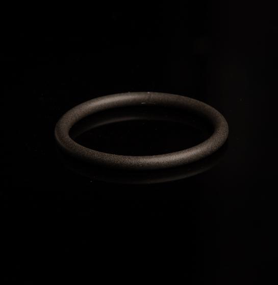
Nickel Aluminum Silicone (SSP2529)
68-durometer. Resists galvanic corrosion. Low outgassing per ASTM E595. Independently tested to MIL-DTL-83528.
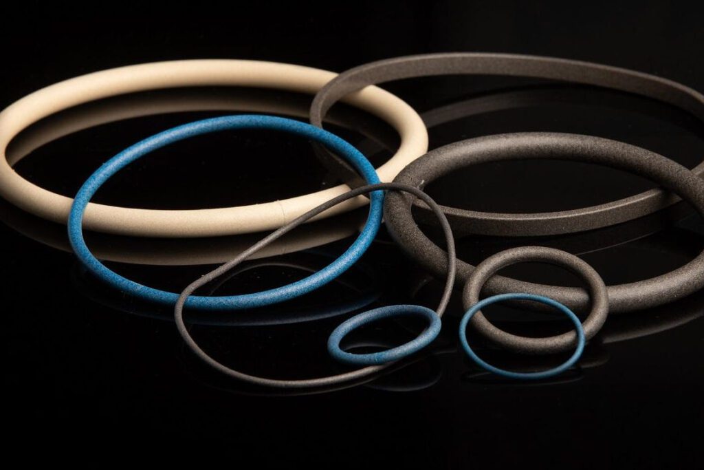
SSP fabricates EMI O-rings in standard and custom sizes, including M83528/002 and M83528/005 part numbers.
Compare our products to EMI O-rings from Parker Chomerics CHO-SEAL, W.L. GORE, and Nolato Jabar. We offer low minimums and short turnaround times.
SSP is a Made in USA, ISO 9001:2105 certified manufacturer. We make our EMI shielding silicones, have our own tool room, and sell you to directly.
EMI O-rings are donut-shaped gaskets that are designed to fit a groove are crushed in place during installation. Like other types of EMI gaskets, they combine shielding against electromagnetic interference (EMI) with environmental sealing.
Ask SSP for a EMI O-rings in M83528 slash sizes, or for custom EMI O-rings for non-military or specialized applications. In many cases, EMI O-rings are replacing standard seals.
In addition to conductive O-rings, SSP makes EMI gaskets that provide environmental sealing and protection against electromagnetic interference. We also supply EMI shielding silicones as sheets, rolls, extrusions, and moldable compounds.
EMI O-rings from SSP use either silicone or fluorosilicone as the base material. Both elastomers can withstand water, ozone, ultraviolet light (UV), and a wide range of temperatures. Fluorosilicones add fuel and solvent resistance.
Electrically conductive fill materials for these elastomeric compounds include silver, silver-aluminum, silver-copper, silver-glass, and nickel-graphite. They differ in terms of cost, conductivity, and typical volume resistivity (VR) – an indirect measure of shielding effectiveness.
Use the table below to compare fillers in terms of cost, electrical conductivity, and volume resistivity (VR): a measure of EMI shielding.
Filler Type | Cost | Electrical Conductivity | Typical VR (ohms/cm) |
Silver | $$$$$ | Extremely Conductive | .0009 |
Silver-Aluminum | $$$$ | Super Conductive | .003 |
Silver-Copper | $$$$ | Super Conductive | .003 |
Nickel-Aluminum | $$$ | Very Conductive | .1 |
Nickel-Graphite | $$ | Very Conductive | .1 |
Use the table below to find and individual EMI O-ring materials from SSP. Note that for M83528 EMI O-rings, we use MIL-DTL-83528 QPL certified elastomers that meet Type A, B, C, D, and K requirements.

68-durometer. Resists galvanic corrosion. Low outgassing per ASTM E595. Independently tested to MIL-DTL-83528.
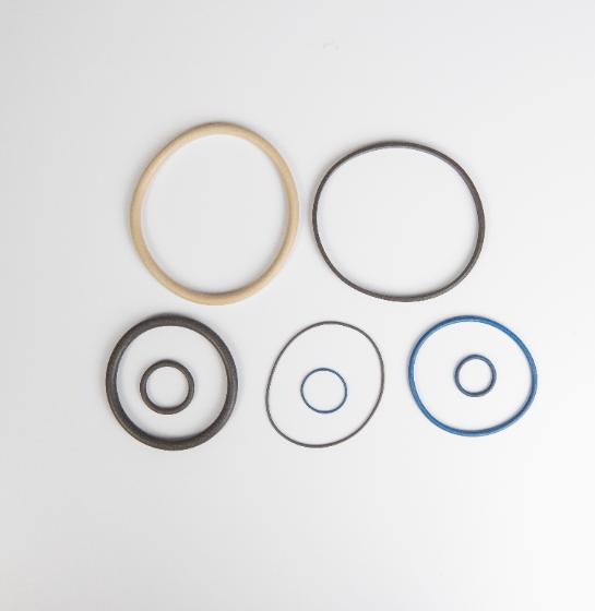
60-durometer. Tested to MIL-DTL-83528. Fuel and solvent resistance.

68-durometer. Resists galvanic corrosion. Independently tested to MIL-DTL-83528 and ASTM B117.
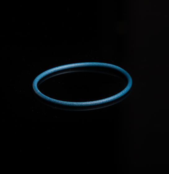
70-durometer. M83528 QPL. Low outgassing. Independently tested to MIL-DTL-83528 and ASTM E595. Fuel and solvent resistance.
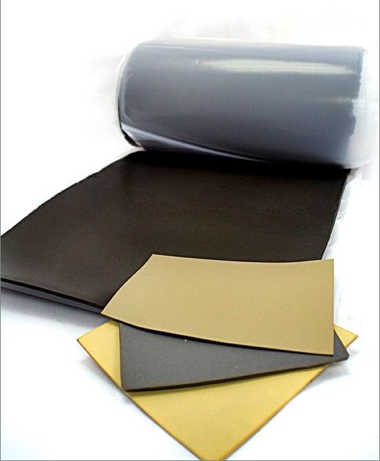
65-durometer. M83528 QPL. Low outgassing. Independently tested to MIL-DTL-83528 and ASTM E595.

72-durometer. Resists galvanic corrosion. Independently tested to MIL-DTL-83528. Fuel and solvent resistance.
SSP offers EMI O-rings made from proven alternatives to these Parker Chomerics CHO-SEAL materials.
CHOMERICS® and CHO-SEAL® are registered trademarks of Parker Hannifin Corporation. SSP is not a Parker Chomerics CHO-SEAL distributor.
SSP also makes EMI O-rings from materials that provide alternatives to discontinued UL 94 V0 flame-resistant EMI shielding from W.L. GORE.
Gore® is a registered trademark of W.L. Gore & Associates, Inc. SSP is not a Gore distributor. Gore® is a registered trademark of W.L. Gore & Associates, Inc. SSP is not a Gore distributor. We manufacturer all of our materials, including EMI extrusions, in-house.
SSP extrudes EMI elastomers in both standard and custom profiles. These extrusions can have very thick or very thin cross-sections and can be solid or hollow. Choose from channels, cords, half-rounds, P-shapes, rectangles, and U-shapes with silicone or fluorosilicone as the base elastomer.
SSP can compression mold EMI O-rings as single pieces or bond them from cut lengths of EMI extrusions, which are extruded rubber profiles. There are advantages and use cases for both molding and bonding.
Tip: Consider whether the requirements you need to meet apply to molded products or bonded products.
There are three ways to bond EMI O-Rings. SSP uses the third method: hot splicing (vulcanizing) with a conductive silicone adhesive.
When are molded EMI O-rings the right choice? Consider the example of a designer who orders prototypes of molded EMI O-rings with a 0.93 in. cross-section and a 4.7-in. diameter.
The cost is $2500 for a small, one-cavity mold and the lead time is 8 weeks. Fit testing reveals an issue with the enclosure’s dimensions, and the designer needs EMI O-rings with a diameter of 4.9 in. instead. New tooling for another $2500 is ordered, and the lead time is another eight weeks. By the time fit testing is successfully completed, the designer has paid $5000 for tooling alone and waited 16 weeks just to confirm the prototype gasket works.
If the designer had ordered hot-spliced EMI O-rings instead, the savings in time and money would have been significant. Instead of larger and smaller molds, a single hot-splice tool could have been used. The designer could have received samples in both 4.7 and 4.9 in. as well O-rings in an intermediate diameter of 4.8 in. If the designer discovered that the EMI O-ring diameter of 4.7 in. was too small, no additional tooling would have been needed. Production for 4.9-in. diameter O-rings could then have begun using the same hot-splicing tool.
Recently, SSP supplied hot vulcanized EMI O-rings to a company that needed to replace EMI gaskets that had failed electromagnetic compatibility (EMC) testing. The need was urgent, but the company wasn’t even sure which O-ring cross-section and inner diameter (ID) were required. Nevertheless, they searched Google and contacted various suppliers of molded and bonded products.
The company received numerous quotes for molded EMI O-Rings but would have to pay $5000 per mold and wait 8 to 12 weeks for three samples in different sizes to arrive. The $15,000 in total tooling costs and the high minimum order quantities (MOQs) were not cost-effective. Plus, the production run would require 12 weeks of lead-time for the mold and two weeks of manufacturing time for a total of 14 weeks.
Next, the company found a gasket fabricator that could bond EMI O-rings from conductive cord stock. The lead times and MOQs were less, but the glue that was used for cold splicing could not withstand the application’s low-temperature requirement. Because the bonding agent was not electrically conductive, there was also an EMI pathway risk.
Finally, the company engaged SSP and leveraged our conductive hot vulcanizing process. For each of the three EMI O-ring samples, our lead time was just one week. SSP did not charge the company for the samples, and there wasn’t a tooling charge either. The conductive silicone bonding agent was rated for the same temperature as the cord stock, and there wasn’t a “hard spot” or EMI leakage concerns.
Bonded EMI O-rings from SSP use tooling that’s faster and less expensive to produce. Because we build the tools and extrude the EMI cords in-house, we can supply you with more prototypes than if you’d waited for a single molded one. The bonding method that we use also reduces the risk of EMI leakage.
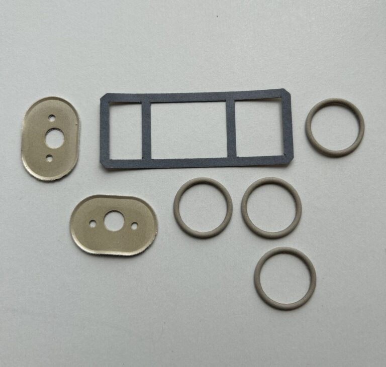
Molded EMI O-rings and custom EMI gaskets from Specialty Silicone Products (SSP).
Both provide environmental sealing and EMI shielding, but conductive O-rings are designed to fit a groove and are crushed into place. They have a distinctive donut-shaped appearance. EMI gaskets can be flat or have specific cross-sectional profile (e.g., hollow D) or shape. In addition to flat gaskets and extruded gaskets, some EMI gaskets are molded into specialized shapes as shown in the image above.
EMI O-rings are electrically conductive because they are they are made of silicones and fluorosilicones that contain specialized fillers. Normally, elastomers are electrically insulating; however, compounding them with metal, bimetallic, or metal-coated particles imparts electrical conductivity. This is why EMI O-Rings are also called conductive O-rings or electrically conductive O-rings.
Fluorosilicone provides enhanced chemical, fuel and oil resistance. Fluorosilicones also resist extreme temperatures and have broader temperature resistance, including to lower temperatures.
Sometimes, SSP receives EMI O-ring inquiries with incomplete or unknown part numbers. If you’re trying to identify the part number you’d like us to make, consider that there are three main sources of this information.
If you cannot identify the original manufacturer of an EMI O-ring, you can find a suitable replacement by determining the product’s specifications.
M83528 EMI O-rings are made from shielding silicones that meet the requirements of the MIL-DTL-83528 specification, and that are fabricated into specific shapes and sizes based on this same U.S. military detail specification.
Conductive O-rings made from MIL-DTL-83528 (M83528) materials are available in what are known as slash sizes. There are two main types of M83528 EMI O-rings. SSP supplies both.
Non-standard EMI O-rings that meet that M83528 requirements aren’t the same as custom O-rings. That’s because M83528 non-standard EMI O-rings still have to meet material and dimensional specifications that are defined in the MIL-DTL-83528 standard, which is sometimes called MIL-G-83528 instead. If you need a custom EMI O-ring for a military or civilian application, contact SSP.
For industrial automation companies that need EMI O-rings, SSP provides both molded and bonded solutions. Molded EMI O-rings are produced as one-piece gaskets. Bonded EMI O-rings use tooling that’s faster and less expensive to produce.
EMI O-ring applications range from electric vehicles and robotic arm to medical infusion pumps for IVs, 5G telecommunications, and aerospace electronics. Here’s where they are used.
Shielded electronic enclosures
Rack-mounted equipment
PCB enclosures
Control panels
Sensor housings
Avionics compartments
Military communication devices
Satellite systems
Missile guidance systems
Radar enclosures
Electric vehicle battery housings
Infotainment systems
Advanced driver-assistance systems (ADAS)
Under-the-hood electronics
Diagnostic equipment
MRI and imaging systems
Patient monitoring devices
Control cabinets in high-noise environments
Robotics
Factory automation systems
EMI-sensitive test equipment
Cell towers and 5G equipment
Base station enclosures
Satellite communication gear
Spacecraft electronics
Satellite shielding
Launch system controls
EMI-shielded camera enclosures
Sensitive listening or scanning equipment
Design News, a trusted source of information for engineers, has published an article about EMI O-Rings by Specialty Silicone Products (SSP). The article, “Designing EMI O-Rings for Shielding and Sealing”, covers applications, dimensions, materials, prototyping, and manufacturing. Molding vs. bonding is a special focus, and SSP shares an example of an engineer who needed prototypes in two different sizes. Dominic Testo, SSP’s Business Development Manager, is the author of the January 25, 2023, Design News article.
Read SSP’s Design News Article
As SSP’s Design News article explains, EMI O-rings are donut-shaped gaskets that are used in applications ranging from electric vehicles, robotic arms, and medical infusion pumps to telecommunications equipment and military and aerospace electronics. When designing EMI O-rings, engineers need to specify cross-section and inner diameter. Material selection is also important, and choices include electrically-conductive silicones that are filled with metal, bimetallic, or metal-coated particles.
Download the White Paper: Particle-Filled Silicones
Whether it’s for prototyping or production, engineers also need to select an EMI O-ring fabrication method. Molding can produce a part in one piece but requires more expensive tooling. Consequently, molding is generally used for higher production. For prototyping and lower-volume production, bonding is more cost-effective. As SSP’s Design News article explains, however, there are several ways to bond EMI O-rings, and only hot splicing reduces the risk of a “hard spot” at the joint.
Download the White Paper: Bonding with Hot Splicing
SSP’s Design News article concludes with a comparison of molding vs. hot splicing for EMI O-rings with a 4.7-in. diameter. As is sometimes the case, fit testing revealed that the specified diameter for this prototype was too small. Because the EMI O-ring was molded, new tooling was needed for a larger 4.9-in. diameter product. This increased costs, extended prototyping, and delayed the start of production. With hot splicing, a single lower-cost tool could have yielded multiple sizes at a lower cost and in less time.
Specialty Silicone Products (SSP) makes conductive silicones for EMI O-Rings at its ISO 9001:2015 certified facility in Ballston Spa, New York (USA). If you need higher EMI O-ring volumes, SSP can mold products for you. If you need prototypes or lower volumes instead, SSP can provide you with hot-spliced EMI O-rings that are bonded with a conductive silicone. This approach reduces the risk of creating a “hard spot”, helps to avoid EMI leakage, and produces a joint with better temperature resistance than acrylic can provide.
As a follow-up to its Design News article, SSP is offering EMI O-ring samples to engineers who are developing products such as EVs, robotic arms, infusion pumps, 5G communications, and defense and aerospace electronics. Samples of the EMI O-ring kits are limited, so act now to find out if you qualify. Contact SSP online for more information.